Pesticide residue detector
Veterinary drug residue detector
Food safety detector
Food additive detector
Bacterial and microbiological detector
Food pre-treatment integrated machine
Soil and fertilizer nutrient detector
Plant Physiology Detector
Water quality detector
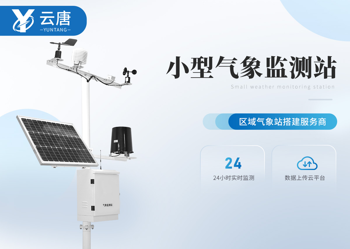
Meteorological monitoring station
Pesticide residue detector
Veterinary drug residue detector
Food safety detector
Food additive detector
Bacterial and microbiological detector
Food pre-treatment integrated machine
Soil and fertilizer nutrient detector
Plant Physiology Detector
Water quality detector
Meteorological monitoring station


model:YT-QX08
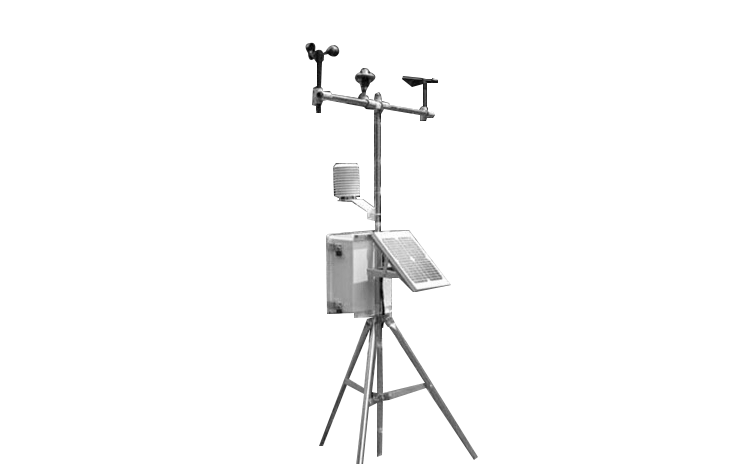
Agricultural and forestry automatic observation instrumentApplied in meteorological research, agriculture, forestry, environment, and other fields, and suitable for field scientifi···
 technical support
Yuntang Technology
One click access to quotation WeChat Scan Code Add Technical EngineerWhatsApp:+86 18866361895
WeChat:+86 17865361250
Email:yuntang@foxmail.com
closeDetails
Picture and Text Introduction
Related Cases
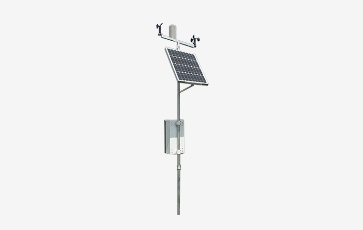
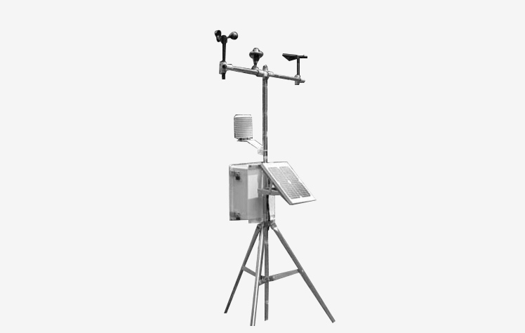
Agricultural and forestry automatic observation instrument
Applied in meteorological research, agriculture, forestry, environment, and other fields, and suitable for field scientific research and experimental applications.
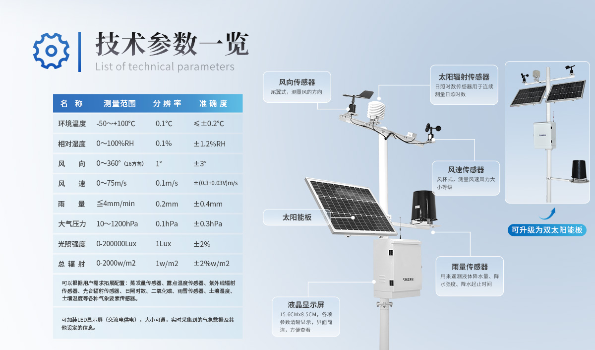
Parameter configuration of meteorological observation stations:
·Air temperature: -30~70 ℃ Accuracy: ± 0.3 ℃
·Air humidity: 0-100% accuracy: ± 3%
·Wind speed: 0-60m/second, accuracy: ± 1m/s
·Wind direction: 16 degrees, namely 0 degrees, 22.5 degrees, 45 degrees
·Rainfall: 0-50mm/hour Error: ± 4%
·Atmospheric pressure: 50-110Kpa, accuracy: 15 digits
·Carbon dioxide: 0-2000ppm, 0-5000ppm, 0-10000ppm Precision: ± 4% FS+3%
·Lighting: -20~80 ℃ Accuracy: ± 2%
◆ Actual application and functional implementation
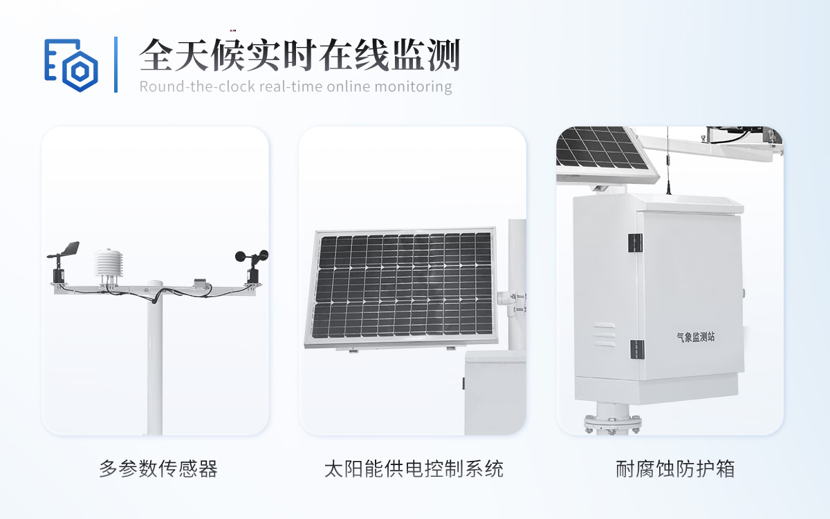
1. HM-NL agricultural and forestry automatic observation instrument, used for all-weather on-site monitoring of meteorological elements such as wind speed, direction, rainfall, air temperature, air humidity, light intensity, atmospheric pressure, etc. It can be connected to the computer through professional data collection communication cables, and the data can be transmitted to the meteorological computer meteorological database for statistical analysis and processing.
The 2HM-NL agricultural and forestry automatic observation instrument is composed of meteorological sensors, meteorological data recorders, and electrical equipment
The components include the source system, field protection box, and stainless steel bracket. Sensors for wind speed, direction, rainfall, atmospheric pressure, etc. are meteorological specific sensors with high precision and reliability. The meteorological data recorder has meteorological data collection, scheduled storage of meteorological data, parameter setting, friendly software human-machine interface and standard communication functions, graphical data display, wired communication mode, and can run in a Windows 2000 or above system environment. It stores data in the format of
Excel standard format, can generate meteorological data charts for other software to call.
Wired transmission method: It is connected to the monitoring center PC through a standard USB communication interface
Wire connection, real-time transmission of collected data.
Wireless transmission method: As long as you can access the internet, you can browse web pages through GPRS wireless transmission to view and analyze data
Actual application diagram of field automatic observation instrument
Communication method: USB interface or 485 communication or wireless transmission
Power supply mode: dry battery, 220V power supply, solar power supply optional
The system is installed on a meteorological bracket, with a compact size and rain and theft resistance.
Sensor interface diagram: Using standard aviation plug wiring standards, easy to plug and unplug, waterproof and safe.
Equipment functions and characteristics
1. Battery powered. Stainless steel bracket, with a total height of 2.3 meters or 4 meters, is more sturdy, greatly improves wind resistance, has a simple appearance, and is very easy to disassemble and install; The bracket is divided into three sections, which are detachable and easy to transport and carry
The software is powerful and can import data from the collector into a computer and store it as an Excel spreadsheet file for further data processing by other analysis software.
2. Communication method: USB communication, storage interval, data reading, and data export can be set according to needs. Or it can use GPRS wireless transmission, as long as you can access the internet, you can view data
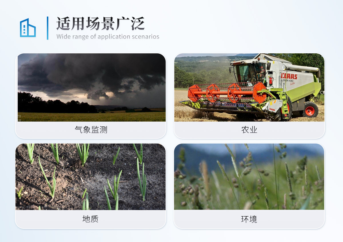
3. Scope of application:
Applied to meteorological research in areas such as meteorology, agriculture, geology, and environment. And suitable for field scientific research and experimental applications.
4. Data storage space:
40000 data storage spaces
5. Data submission and communication:
Data can be extracted from computers irregularly or wirelessly.
Communication connection diagram:
Applicable scope:
This sensor can measure the wind direction in the outdoor environment, measuring in different directions: east, west, south, north, southeast
There are sixteen directions including southwest, northwest, and northeast, which have high cost-effectiveness. This instrument is widely used
In fields such as environmental protection, meteorology, agriculture, forestry, water conservancy, construction, scientific research, and teaching.
Appearance specifications:
Compact and lightweight in appearance, aesthetically pleasing and sturdy, easy to carry and assemble, with a well-designed wind vane shape,
It has an accurate positioning effect on the natural atmospheric wind direction. The specifications are shown in the following figure:
rain sensor
Technical parameters:
Rain bearing diameter: φ 200mm
Measurement range: ≤ 8mm/min
Resolution: 0.5mm
Error: ± 4%
Weight: approximately 3.5 kilograms
Output signal: single reed switch on/off, 4PLUS/MM (anti-interference resistance of 100 ohms and capacitance of 0.01)
Microfabrication
Function and features:
Small size, easy to install; High precision and good stability
Good linearity, long transmission distance, and anti-interference ability
Design mesh holes at the funnel to prevent debris such as leaves from blocking the flow of rainfall
The support system of the tipping bucket components is well manufactured with low friction torque, resulting in sensitive flipping of the tipping bucket components,
Stable performance and reliable operation
The instrument casing is made of stainless steel, which does not rust and has good appearance quality
The rainwater outlet is made of stainless steel sheet and is integrally punched and pulled, with high smoothness and small error caused by water retention
There are horizontal adjustment bubbles inside the chassis, which can assist in adjusting the equipment to the optimal level at the bottom angle
Working principle:
The rainwater collected at the water inlet is fed into a metering hopper through an upper cylinder (funnel) - the hopper is
Working environment temperature: -20~80 ℃
Injecting engineering plastic into two equal volume triangular chambers using a middle partition. It is a mechanical bistable structure, where when one chamber is filled with water, the other chamber is in a waiting state. When the volume of rainwater received reaches the predetermined value of 0.5mm, it overturns due to gravity and is in a waiting state, while the other chamber is in a water receiving working state. When its water intake reaches the predetermined value, it flips over on its own and is in a waiting state. Magnetic steel is installed on the side wall of the flip bucket, which scans from the side of the dry tongue reed tube when the flip bucket flips, making the dry tongue reed tube turn on and off. For each flipping of the bucket, the dry tongue reed tube is connected and sends a switch signal (pulse signal).
Introduction to Software Installation and Use
⊙ Installation of upper computer software
(1) Operating environment
(2) Software installation interface
(3) Other software installation interfaces
(4) Installation of USB data cable drivers and other driver installations
(5) Program generation icons and program menu items
(1) After completion, a "data collection icon" will appear on the desktop as shown in the right figure:
(2) Program menu items:
(6) Using USB data connection cable
After installing the recorder software, connect the USB communication cable in the recorder accessories to the computer
The USB port of the machine. The system will automatically install the USB driver:
Detailed Introduction to Sensors
Air temperature, humidity, light, atmospheric pressure sensors
The air temperature, humidity, and atmospheric pressure sensors are placed inside a radiation proof ventilation hood, also known as a lightweight louver box. This product is made of high-tech and high-quality UV resistant materials, which can effectively block UV radiation under natural conditions, prevent rapid aging of instruments and meters in harsh outdoor conditions, and reduce measurement errors caused by strong light
The standard configuration of the product is 9 anti radiation discs per set, which are detachable. The number of radiation protection discs can be adjusted according to the actual size of the instrument during use. Compared with wooden louver boxes, lightweight louver boxes have the advantages of small volume, light weight, and easy installation
Technical parameters:
Temperature range: -30 ℃ to 70 ℃
Temperature accuracy: ± 0.3 ℃
Humidity range: 0-100%
Humidity accuracy: ± 3%
Atmospheric pressure range: 50-110Kpa (unit conversion: 1Pa=10bar)
Wind speed sensor
Technical parameters:
·Accuracy: ± 1m/s
·Starting wind speed: 0.2 m/s
·Range: 0-60 m/s
·Output signal: Pulse (each pulse corresponds to 0.88m/s)
·Power supply voltage: 5V~24V DC
Function and features:
Compact in size, easy to carry, and easy to install
High measurement accuracy, wide range, and good stability
Reasonable structural design and excellent appearance quality
Good linearity of data information, long signal transmission distance, and strong resistance to external interference
⊙ Upper computer software operation
(1) Open software
In the main interface of the software, you can view the starting collection time and historical data of the recorder
Storage time interval, device memory usage, and power level.
(2) Software Main Interface Button Description
Data chart display area: can view historical lists, historical curves, immediate numbers, and immediate curves.
Common function button area: [Read History], [Retrieve Data Now], [Upper Computer Settings]
【 Clear Recorder 】, 【 Data Calibration Table 】, 【 Setting Scheme 】
(3) Read historical data operation (located on the software main interface)
[Read History] Read all the historical data recorded by the recorder, and the length of the reading time is determined
Set storage intervals and storage times.
(1) Click [Read History] to extract the historical data recorded by the recorder into the data display area:
⑵ Users can view the curve display status of the data:
⑶ Click the [Data Export] button to export and save historical data as an external file
(Excel format):
Using EXCEL office software to open saved files
Insert the chart into the Excel menu with the mouse sequentially, and the data can be displayed in different curve ways.
(4) Read immediate data operation (located on the software main interface)
【 Immediate data retrieval 】 It can collect current parameter data immediately and observe the current data in real time
Environmental parameters.
(1) Click on 【 Immediate 】 to extract the collected data into the data display area:
⑵ Users can view the curve display status of immediate data:
⑶ [Immediate retrieval] can be divided into two methods: manual retrieval and automatic retrieval:
① Click the 【 Retrieve Now 】 button once to manually collect data.
② Set the time interval for automatic data collection, then click the [Start] button to automatically collect data at a certain interval and extract the data in the data display area. At this point, the [Start] button in the interface has changed to the [Stop] button. You can stop it as needed, as shown in the following figure:
Click the [Data Export] button to immediately export and save the data as an external file (Excel)
The format of the resulting Excel file is the same as that of the file stored in the historical data. Therefore, it is not necessary to
Further elaboration.
(5) 【 Upper computer settings 】 (located on the software main interface)
【 Upper computer settings 】 The name of the upper computer data channel, data upper and lower limits, and communication can be set
Functions such as communication delay and data correction.
Click on 【 Upper Computer Settings 】 to enter the following dialog box:
(1) A series of basic parameters can be set, such as modifying channel names, viewing and modifying formulas.
(2) Channel Properties
A. Name: Modify the name of the current channel, which can be set to Chinese for easy memory. repair
The changed name will be applied the next time the recorder is connected.
B. Formula: Due to the difference in the way devices represent data compared to humans
The formula is to convert the data of the device into data that can be understood by humans, such as converting the temperature from 780 on the lower computer through the formula (AD/10-50) to an understandable 28 degrees.
C. Offset: After using the device for a period of time, it is inevitable that there will be an offset phenomenon. Using offset
The function can remove the offset of the device. For example, when the current actual temperature is 30 degrees and the display shows
If the temperature is only 28 degrees, writing 2 here can offset up by 2 degrees, if necessary
If it is 2 degrees lower, enter -2.
D. Alarm upper and lower limits: When the value of historical or immediate data of a certain channel is not within the alarm upper and lower limits
When within the range, the data is displayed in red font to indicate that the current channel data is abnormal.
(3) Channel calibration table column
① When the equipment leaves the factory, the sensor data is usually calibrated, but due to the following reasons
Due to the need for recalibration:
A. Hope to improve equipment accuracy
B. Used in special environments
C. Using different sensor schemes
D. The device has been used for a period of time and there may be data offset, which may require calibration again.
② There are two columns in the channel calibration table:
The first column is the raw data: that is, the data values before correction.
The second column is the corrected data: that is, the corrected data. For example, if the first column value is 10, after correction
When the value is 10.2 and the number taken from the device is 10, it displays 10.2.
③ The import and export functions in the channel calibration table are to convert the calibration data of the current channel into Excel
Export the format to another location for easy re import in the future.
(4) [Manual addition] Button function (for humidity)
After knowing the correspondence between the original data value and the actual data value, and obtaining
When obtaining multiple sets of control data, the manual addition function can be used. For example: Currently, the ring knife method has been passed
Obtain high-precision data and measure multiple raw data with immediate retrieval function. The data is as follows:
Raw Data Ring Knife Data
20 20.1
21 21.2
21.5 21.6
The method of adding is to click the [Manual Add] button, and then follow the prompts to operate:
① According to the dialog box prompt, write the data in the first row and first column as 20, and click [OK]
② According to the dialog box prompt, write the data in the first row and second column as 20.1, and click [OK].
③ Repeat steps 1 and 2 to input all data into the upper computer.
After completing the input and saving the settings, the correction will be applied immediately
(5) 【 Immediate retrieval 】 Button function
Reference channel - calibrated channel
There are two types of immediate data retrieval:
① Correction through reference channel
If a certain channel has been calibrated and applied, and the current reference channel selects the calibrated channel
Channel, clicking on 【 Data Now 】 will retrieve the current data of the benchmark channel and the current channel data,
Then it is automatically written into the calibration table, and after writing, a calibration point is completed.
5) 【 Immediate retrieval 】 Button function
Reference channel - calibrated channel
There are two types of immediate data retrieval:
① Correction through reference channel
If a certain channel has been calibrated and applied, and the current reference channel selects the calibrated channel
Channel, clicking on 【 Data Now 】 will retrieve the current data of the benchmark channel and the current channel data,
Then it is automatically written into the calibration table, and after writing, a calibration point is completed.
② Correction without reference channel
When you know the current actual data, clicking on "Retrieve Now" will skip "Enter Original Data"
One step (because when clicking to retrieve data immediately, the current channel's value will be automatically retrieved), and the dialog box will
Directly pop up the request to input the corrected data value, and after writing it, complete the correction of a calibration point.
Note: The calibration table must be saved and will only be applied when exiting the upper computer settings. Channels that have not been applied cannot be used as reference channels.
(6) Communication delay
When using a slow device, modifying the communication delay value can make the system wait for the device to finish
Complete the operation without considering it as an operation timeout. The default communication delay value of the speedometer is 15 seconds.
(7) [Export Configuration] Button Function
Export the current system configuration as a file for easy data import in the future.
(8) 【 Import Configuration 】 Button Function
Load the previously exported configuration and restore it to the previous data.
Note: Importing configurations will overwrite the current configuration
(9) After the relevant settings are set
① Click [Confirm] to save the current modifications and return to the main interface of the program.
② Clicking [Cancel] will cancel all the modified upper computer settings and return to the
The main interface of the program.
(6) Data Correction Table (located on the main interface of the software)
This data calibration table is also known as the equipment data calibration table. Equipment data calibration table and located in the main
The data calibration table in the 【 Upper Computer Settings 】 on the right side of the interface has the same function, but the device data calibration
The storage location of the table is within the device.
Interface Description (The numbers ① - ⑨ below are the displayed numbers in the figure)
① Select one of the options in the dropdown box and set the maximum number of available calibration tables that can be set
50 sets of calibration tables
② You can choose the table item you want to set currently
③ The name of the currently selected calibration table
④ Existing data in the current calibration table
⑤ Write the data to be added here (actual data: actual final displayed data value; original)
Initial value: The initial data value collected by the controller
⑥ Use this button to download the currently set configuration to the device
Note: The corresponding format of the calibration table is, and the channel data corresponds one-to-one with the calibration list items.
Data calibration process: The initial data collected is compared and determined to fall into two calibration groups
Between points, and then, using the principle of two point straight lines, obtain the desired actual data through calculation
Value.
For example, enter the following data items in sequence, for example, select Table 1, enter,
Actual data value (A) Original value
(7) [Setting scheme] (for humidity) (located on the software main interface)
Set up a scheme for channel calibration tables. Click on [Set Scheme], and the following dialog box will pop up:
Enter the scheme you want to use, which can be selected in the Data Correction Table. If Table 1 is selected,
Then write "1" (excluding quotation marks) here, and select 0 to not correct.
If the selection is successful, it will prompt that the operation is successful, as shown in the dialog box on the right:
(8) [Clear Recorder] (located on the software main interface)
[Clear Recorder] Clear the recorder data, reset the start time and storage
Time interval.
Warning: This operation will clear all data in the recorder. Please make sure to clear the data before clearing it
Export and save.
(1) Clicking the 【 Clear Recorder 】 button will bring up the following dialog box:
Then there are two ways for you to choose from for clearing:
① Select the immediate start mode, which will immediately start collecting and storing data once, according to the settings
Automatically collect and store data.
② Select delayed start and restart the speedometer after reaching the set time point.
Attention:
(1) The set time point for delayed start cannot exceed 23:59 on the same day.
(2) The minimum time interval of the recorder is 1 minute.
(9) Installation of batteries
When installing a battery, attention should be paid to the positive and negative poles of the battery. Incorrect battery installation can cause damage
Damage to the recorder.
The positive and negative poles of the battery are shown in the following figure:
1. Open the battery box as shown in Figure 1
Figure 2
2. Open the front cover of the recorder and install it according to the positive and negative terminals of the battery, as shown in Figure 2:
(10) Viewing battery level (located on the software main interface)
1. Open the recorder using the upper computer software.
2. After opening, the software interface of the recorder will display a five grid battery indicator, indicating the number of grids
The more it is, the higher the battery level. If there are 0-2 battery levels, please closely monitor the usage of the recorder and replace the battery in a timely manner.
3. Schematic diagram (the box represents the battery level, and the current battery level is displayed as full):
⊙ Common fault phenomena and solutions
1. Communication failure, unable to connect to the computer
After inserting the communication cable into the computer, check if there are any findings in the ports (com and LPT) of the device managerThe newly inserted prolific USB TO Serial COMM PORT communication interface. If not, it indicates that the communication cable driver is incorrect and the software needs to be reinstalled. If everything is normal, take a look at the port number corresponding to the prolific USB TO Serial COMM PORT. In the accompanying upper computer software, select the corresponding port, confirm the correct connection to the recorder, and then try again.
2. The data is abnormal, and the collected data is significantly high, even displaying thousands of humidity values.
The battery level indicator shows that the battery is full, but the data is abnormal, which may be due to poor battery quality
Causing it, you can try again after replacing the battery.
3. Precautions for outdoor use
This recorder is protected by a waterproof box, and the inner side of the buckle is lined with a sealing strip to prevent rainwater
Enter the box, but if the recorder is placed too low (such as directly on the ground), or if it is placed
Incorrect placement method (flipping the recorder upside down or placing it flat on the ground) may pose a risk of water ingress into the outlet hole, thereby affecting the use of the recorder.
⊙ Precautions for use
warning
Not following the wiring sequence may cause damage to the equipment and the instruments connected to it
When the input power exceeds the maximum connected power of the device, it will cause damage to the device
damage
take care
Please read this manual in its entirety before use
Correctly connect device lines
First, confirm that
* Check if the device is the same as the one you purchased
* Check if the appearance of the equipment is damaged
* Check if the equipment accessories are complete
⊙ Maintenance and upkeep
This instrument is a technological product with excellent design and functional principles, and attention should be paid to maintenance and upkeep. The following suggestions will help you effectively use maintenance services.
* Avoid scratching the instrument, maintain the integrity of the external protective film, and increase the service life of the instrument
When using the instrument, please fix all connecting parts firmly to avoid damage to the instrument
Rough handling of instruments can damage internal circuit boards and precise structures
Do not apply paint to the instrument, as it may block debris in the detachable components and affect the positive angle
Regular operation
* Use a clean and dry soft cloth to clean the outside of the instrument
* Regularly check the power level of other configured devices to ensure that the instrument is working properly
Software and control functions
User login
Specify user permissions, non users cannot log in to the system, ensuring system security. Settable
Permission to modify users and passwords. There are two levels of permissions: viewing permission and parameter modification permission
Limit.
System monitoring
Regularly record all parameter data.
Real time curve
The real-time trend curve can display the data collected by the system in the form of a real-time curve,
To facilitate the observation of system status.
Historical curve
It can display the daily, monthly, quarterly, and annual parameter change curves of each measurement parameter. Based on this curve
Reasonable system parameter values can be set.
WeChat:+86 17865361250
WhatsApp:+86 18866361895
Email:yuntangzhineng@foxmail.com
Copyright @ 2019-2022 Shandong Yuntang Intelligent Technology Co., Ltd All Rights Reserved. Copyright Source manufacturer of pesticide residue detector, food detector, bacteria detector
 WeChat


TOP
 Leave us a message